First of all I would like to thank Kemosabe & IS973800 for all the help they have given on this project.
The replacement Overhead Console Cover arrived on Friday and since it was a beautiful day here in Omaha I decided to not wait for the weekend. I picked up an almost new Garage Door Transmitter at a local wrecking yard last week. The Overhead Console Cover is part # 25978347, COVER-RF CNSL OPG *TITANIUM-58 and cost $55.99 plus shipping. Just about any Transmitter from a GM vehicle will work. Just look for the same shape buttons. I pulled transmitters from a Jimmy, 1500, Yukon, and Trail Blazer. They all look the same and all had LEDs (instrument lights). The rubber buttons come in grey or black. I used black to contrast with my grey (Titanium) interior.
Step by Step:
1. Wash your hands so you don’t get your headliner dirty. I like to program the Garage Door Transmitter before I test it. Check YouTube for HomeLink instructions.
2. Pull original Console down. Gently pull down one corner and work a screwdriver in so you can get a finger in. It’s tight but will come down with a little force.
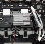
3. Everything is powered from the one Grey connector. Note that there are more wires on the headliner side than on the Console side. Not all the wires pass through to the Console. Wires number 6 and 8 (below) will be needed to power the Transmitter.
The Console side of the connector has empty holes where you need pins. You could try to find the pins from another connector (auto parts store or junk yard). I decided to use a second connector (sub connector) to supply the Battery Voltage and Instrument Lights.
4. Swap the guts of your old Console to the new Console. This is a good time to replace the Courtesy Lights with LEDs. (LED’s are polarity sensitive so test them in the Console. I used a 9v battery.)
5. Install the Garage Door Opener.
6. Unwrap about 1 inch of the Console's wiring harness. Using a Quick Connect splice the Transmitter’s ground wire to the Black Wire from the grey connector.
7. If you are using a 2nd connector to power the Transmitter go to step 8.
If you installed pins in the # 6 and 8 slots of the grey connector, run a wire from pin 8 (Instrument Lights) to the center pin on the Transmitter’s connector. Battery Power (pin 6) goes to the Inner Most pin on the Transmitter. You are done and ready to test your new Console. Go to step 10.
8. If you used a second connector to power the Transmitter, be sure it’s polarized (can’t be plugged in backwards). Using 4 inch (#16 or #18) wires solder (or crimp) the sub connector and wrap with electrical tape. Make the Headliner side of the sub connector (female side) but don't wrap with tape yet.
9. In your vehicle, unwrap about 2 inches of the harness, use Quick Connects to splice to the #6 and #8 wires above the headliner.
10. Connect your new Console and test all functions. A darken garage is the best place to see the buttons on the Garage Door Opener, Instrument Lights on.
11. After testing wrap all loose wires with electrical tape. Install Console in headliner.
I took lots of photos of the installation but unfortunately get an error when I try to upload them here. (
https://picasaweb.google.com/103987703483262815875/Misc#)
Connector Pinout
PIN 1: OG - Courtesy Lamp Voltage
PIN 2: BN - Sunroof Switch Open Signal (C3U)
PIN 3: OG - Sunroof Switch Close Signal (C3U)
PIN 4: L-BU - Front Sunshade Switch Open Signal (C3U)
PIN 5: YE - Front Sunshade Switch Close Signal (C3U)
PIN 6: RD/WH - Battery Positive Voltage (UG1)
PIN 7: PU/WH - LED Dimming Signal
PIN 8: GY - Instrument Panel Lamp Voltage
PIN 9: GY/BK - Courtesy Lamp High Control
PIN 10: BK - Ground
PIN 11: GY - Cellular Microphone Signal (EU1)
PIN 12: BARE - Ground (EU1


 - the connectors are different. Current is grey - maybe 8 pin and new on is green, maybe 16 pin.